FreeCAD Mosaic Maker

These are just the colours that happened to be in the printer. I think they worked rather well.

I’ve been playing around with Python programs in FreeCAD for a while. Today I did a bit of image processing. The little program I’ve built reads in an image, resizes it, reduces the colour depth to 4 and then drops out four STL files, one for each colour. These can then be combined in the slicer to make a low-res picture.

The pictures look better the further you are away from them. A bit like me. At the moment I’m using a resolution of 128x128 pixels. I’ve got to tidy the code up a bit, and then I’ll put it all on GitHub.

Making a 130 Year Old Instant Camera

The Camera itself is a work of art

The camera above was a very impressive gadget back in the 1890s. I got it at a camera fair in Boston Spa. It’s a quarter plate camera which takes pictures on glass slides. These are mounted inside a film holder which clips onto the back of the camera. When it was time to take a picture you’d slide back a “dark slide” on the film holder which covers the film surface and fire the shutter. Then you’d slide the dark slide back over the film and try to remember not to expose it again. The film holder has a dark slide on each side, so each holder is good for two shots.

Back home in the dark you’d take the glass slide out of the camera, develop it to make a negative and then create contact prints by exposing photographic paper through the negative. Then you’d post the prints to your friends and head off the chemists to buy some more glass slides, chemicals and paper to repeat the process. Instagram in the time of Queen Victoria.

You can’t get the glass slides any more. But you can get Instax Wide instant film. It turns out that the instant film is around 2 mm deeper than the glass plates and won’t fit in the holders I got with the camera, which is rather annoying. So I thought I’d make my own film holders which are large enough to allow me to use instant film with the camera.

This was the design I came up with. The dark slide (the black thing in the picture above) fits behind the blue outer frame. Then we have the Instax film (you can just see the grey edge of the film sheet) which fits inside top of half of the frame (the red bit). The purple bit at the bottom is the other half of the frame. That will have another outer frame bolted to it and hold a second dark slide. All the parts are bolted together. I have to use this rather complex design because 3D printers can’t really print the kind of overhangs that you’d need to print both sides at the same time.

Pen and Tie Fighter for scale

At the back right is the camera folded up in its little box. On the left at the front is an original wooden film holder. On the right is my 3D printed version. It turns out to be light tight enough to be used successfully. I wouldn’t leave it out in the sun, but as long as you keep it in the shade it works fine. I load it up with Instax film, pop it in the camera, slide open the dark slide, take the the picture, put the film back into an Instax film holder and then run it through an instant camera to process it. It sounds a bit complicated, but it is easy enough. If I make a few more of the holders I can load them all up and then go out and take a bunch of pictures.

On the left is the first ever picture I took with the camera and my film holder. The duck is a bit blurred, but the stuff further back is tack sharp. The picture on the right is not particularly interesting, but it is lovely and sharp with plenty of detail. There’s a light leak down the left because I pulled the dark slide all the way out and a bit of light got in. The finished version has a stop which prevents the dark slide from being pulled all the way out, so that shouldn’t happen again.

I’m going to take the camera to the next hardware meetup and try and take some portraits with it. The film holder designs will be available on GitHub for anyone who has a camera like this and fancies using it as an instant camera.

Instax Film Holders

I’m just wondering if any of my readers have a quarter plate camera from around 120 years ago and fancy using it to take Instax Large photographs but have discovered that the quarter plate film holders are just a tad too large for the prints.

If you are in this position (which I agree is perhaps unlikely) I might have some good news for you. Once I’ve completed the design…

The Curse of the Oversized O

When I was making the tags yesterday I hit an interesting quirk of font rendering. My plan was to make my text exactly fit a tag by setting the size of the text to the height of the tag. This didn’t work because for obscure typographic reasons involving “making text look right” a capital O is rendered slightly larger than the surrounding text. As you can see above.

There were two ways I could solve this problem. I could check the height of each rendered character and scale it to fit exactly in the available height. Or I could just add a margin to the text.

I think I’ll just leave this here..

Infinitely Baffled

The box above took over three hours to print. It’s perfect in every way except one. I’m going to have to print it again. The problem is with the speaker fitting at the bottom of the box. The speaker fits into the circle and is supported by four pillars. But the pillars are too high.

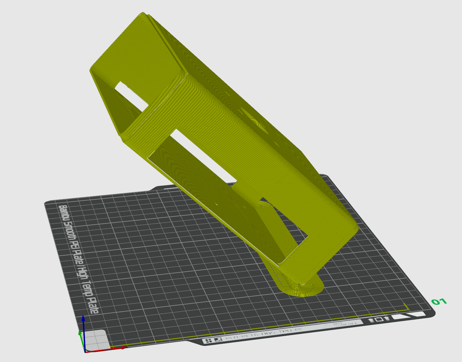
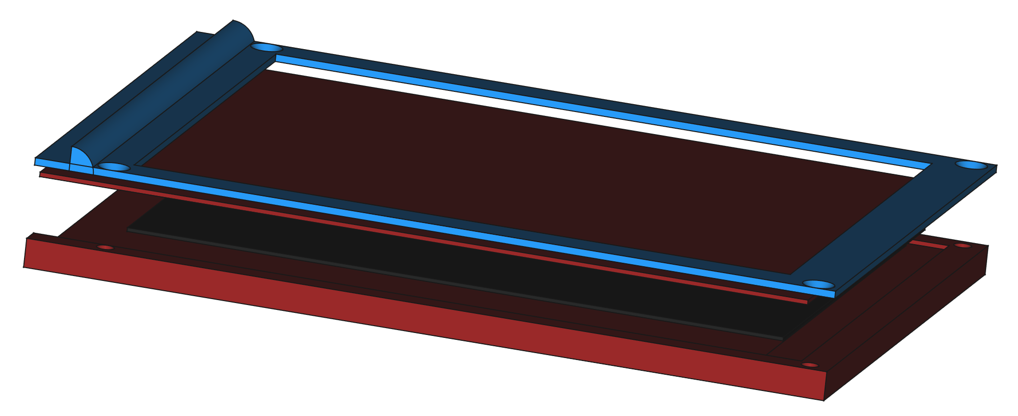
You can see the problem here. If I put the speaker on top of the pillars there will be a gap between the speaker and the hole it fits in. This makes it sound awful. To understand why we have to learn about about how speakers work.

The cone in a speaker goes backwards and forwards, pushing the air in front of the speaker to make sound waves we can hear. We really don’t want to hear anything from the back of the speaker because, although it is also sound, it is going the “wrong way”. The sound term for this is “out of phase”. When air in front of the speaker is being pushed forwards, air at the back is being pulled. If sounds from the front and the back meet up they can interact in ways that don’t sound nice.

Some speakers use carefully designed boxes which take the out of phase sound from the back of the speaker and reflect it in some way to invert the phase so that it adds to the sound. Other speakers solve the problem by putting the speaker in a sealed box from which the sound from the rear of the speaker can’t escape. These are called “infinite baffle” speakers. If you call the thing that we put the speaker into a “baffle” (which sound people do) you can see that an infinitely large baffle would stop any sound from the back of the speaker getting to the listener.

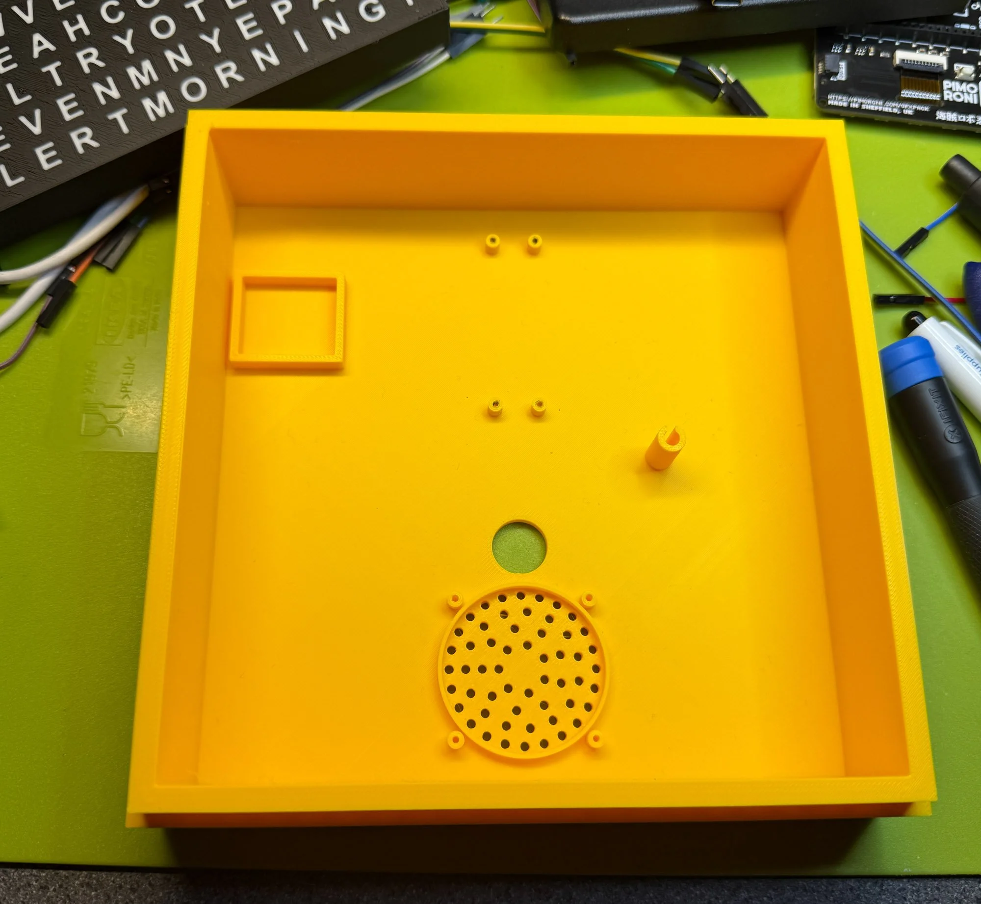
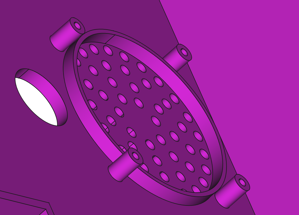
I’m trying to make my device use the infinite baffle principle. That’s why I have the circle that the speaker fits into and seals against. However, if I have a gap between the front of the speaker and the baffle I get sound leakage from inside the box and the speaker sounds rubbish.

So that’s why I reduced the height of the pillars and printed the box again. It makes a surprising difference to the sound. As to why I got this wrong in the first place: I made all the pillars in the box the same height, then I increased the height of the pillars that support the PICO In the middle of the board and that made the speaker pillars higher too.

Update: It’s just occurred to me that I have a hole in the back in the form of the power cable entry. I might convert that into a socket (or add a seal) and see if that makes it sound even better.

Printing Slow

..now with the words “half” and “Quarter”

I’ve been printing wordsearch clocks again. As you do. The first few prints were spectacularly unsuccessful, which was a surprise as my Bambu printer is usually super reliable. The problem was that the first layer that is printed is the white letters. These are very thin and I’ve always found that white filament tends to not stick as well as other colours. The result was a couple of very messy prints that I had to abandon. So, I tried slowing things down a bit.

This is the print speed menu in Bambu studio. You can change printing speed by height, so that the first few layers of a print can be printed very slowly giving the filament time to stick to the bed. I just print the first 4mm of the model at the low speed, but because this is one of the more complicated bits it added over an hour to the print time. But it also worked, which is nice. So now I can make white and black and black and white wordsearches.

Significant Other Charms

These are the finished versions and they’ve printed quite well. The idea is that you have one, and you give your significant other, er, the other. Then, when you meet up you can fit them together (they do fit rather well). Each pair is completely unique (unless you print lots of them I suppose) and symbolises the uniqueness of whatever you think is unique about whatever your relationship is. Oh the romance of it all. I’m putting together some examples of writing Python code inside the FreeCAD design tool, and the charms are one of them. Another is my “Little City”.

Not bad for around 100 lines of code. The examples will all be going on GitHub soon.

Creating Multi-Colour prints from FreeCAD

I need to work on the letter sequencing…

I’ve been working on the self-solving wordsearch for a while now. Today I’ve been creating two different models for the case, one is the white outer case and the other is the black letter grid. I managed to print out a small test piece and I’m quite happy with how things turned out. The idea is that I put lights behind the letters and you can watch the answers appear.

This is the back of the text. There are some bad bits, but they don’t really show

The design is built using Python in FreeCAD which made it very easy to create and align the two models. Next step is to make the full size (16x16) wordsearch and then print it out, which might take a while. Great fun.

Snap Fit Fun

I’m trying something different with 3D printed components. Snap fitting. Rather than using screws and whatnot I’m cutting grooves in one element and putting a lip on the other so that they snap together. It’s all done by the software that makes the panels, and I’ll be able to tweak the size and configuration of the snapping bits. All I have to do now is print the parts and see if they snap together….

Super Secret Encoder

Behold, the super secret encoder. Each spy has their 3D printed encoder strip. Individually they are meaningless, but stack them together and the secret word is revealed. Other words can be entered if required.

You can create your own encoders using a little Python program that runs inside FreeCAD. The code is here: https://github.com/CrazyRobMiles/Python-in-FreeCAD

Might be fun for Christmas messages. It’s never too early to start.

3D Printed Lens Cases

I fancied some 3D printed lens cases. So me and ChatGPT wrote a little Python program that runs inside FreeCAD to make them. I find ChatGPT a useful coding companion. It doesn’t usually get the code right, but it does provide enough insight into how the code is supposed to work to make it much easier to create something that does what you want.

As an additional flourish, we managed to put text on the outside of the case by rendering a TrueType font into a shape and then cutting it out of the case. You can see the results above. Next step is to get some foam and make some inserts to keep the lens nice and safe. I’m going to tidy up the code a bit and put it on GitHub.