Cloud Connected Camping Lights

I was in the Pound Shop over the weekend looking for camping lights. What with we me going camping in a month or so. I'm going to the Electromagnetic Field event at the end of August, and I've been buying sleeping bags and contemplating life under canvas for a few days. 

I found a likely looking light in a camping shop for a fiver but being from Yorkshire I thought I'd take a look at cheaper solutions. I found the lights above, packed in a nice little box, for a pound a pop. Astonishing value, so I bought four. 

Then I got to thinking about making the light more interesting. I've done this kind of thing before and I had some pixel rings and Wemos devices lying around, so I thought I'd have a go. Worst case I'd break a light that cost me a pound. 

This is the light dismantled. I undid the screws that held the base on popped the top off and then slid the transparent cover down and off the bottom of the light. Then I used a knife blade to pop the plastic reflector off the top to reveal the pcb that holds the 11 white leds. I'm going to replace this with a 16 led neopixel ring which just fits. You can get these rings for around 8 pounds, or much less if you're prepared to wait for them to arrive from China. 

The plan is to fit the led ring a shown above, drill some holes in the plastic support and run the wires behind through them, providing a connection and also holding the ring in position. I can bring in the hot glue later if I want to make things even more secure. 

I held the led ring in position, scratched marks on the reflector and then drilled the holes. I'm not very pleased with the bottom hole, but I don't think anyone will see it. I'm only using three of the connections, but I drilled four holes so I didn't have to remember which was the one I don't need. 

These are the wires that I made up for the connections to the led ring. I used solid core wire. I'm connecting to the ground, 5Volt and Data input lines using black, red and white wires. The colour of the wires doesn't matter much, as electricity doesn't seem to care about wire colour.

If you read the Adafruit help pages for the Neopixel ring they talk sensible things about series resistors and capacitors that you can add to improve the signal to the led ring and reduce the chances of damage. I'm leaving those out because I like to "live on the edge", but you might want to add them if you build a light like mine. 

This is the led ring after I fitted it to the reflector with the wires pushed through the appropriate holes. Looks quite tidy to me. Next up we have to take a look at fitting the processor board to the light. 

This is how the lamps are made. They have a slide switch which controls power to the led ring. It's a bit hard to see, but there's a series resistor on the positive side which is wired from the battery terminal to the switch. I'll use the switch to turn the device on and off. 

I'm going to add an ESP8266 device on the Wemos platform. I love this device and configuration, and it just fits. It will give me WiFi for connectivity and my plan is to port my wedding light software onto the Wemos platform. 

This is the device with the signal and power wires soldered in. For some reason I was nervous about soldering solid core wires onto the Wemos PCB and so I soldered in some jumper cables instead. I've done this before and it's a good trick. Rather than soldering a socket and then plugging into it (and having the worry that the plug might come out) instead I just solder the plug straight in. I'll cut the plugs off the other end and wire things up by twisting wires together, soldering them and covering with heatshrink tubing. Probably not as posh as using proper connectors, but much cheaper and at least as reliable.

I'm using one data pin to control the lights. Just because I'm moody, I decided to solder this wire in directly. I stuck the Wemos device onto the back of the reflector using some sticky velcro tape that I got from Maplin. I'm really going to miss that shop.

This is the completed processor fitted to the reflector. I've done the wiring and so I now just have to power up the device to get it going. This is also a useful stage to reach because now that I've connected the power lines for the leds and the processor together I can plug the Wemos device into the PC using a USB cable and test that the lights work. So I did this. There will now be a short break while I get the software together. 

Writing the software took longer than I expected because I found a bug. However, once I'd fixed that I turned my attention to the base of the light. I soldered some new wires to the switch and onto the battery terminals. Now I just have to connect the red and black cables to the ones on the processor and I'm good to go. 

This is the lights and the power all soldered together. I've made the wires much longer than they need to be, this is so that it will be easy to pop out the reflector and re-program the Wemos when I find another bug.

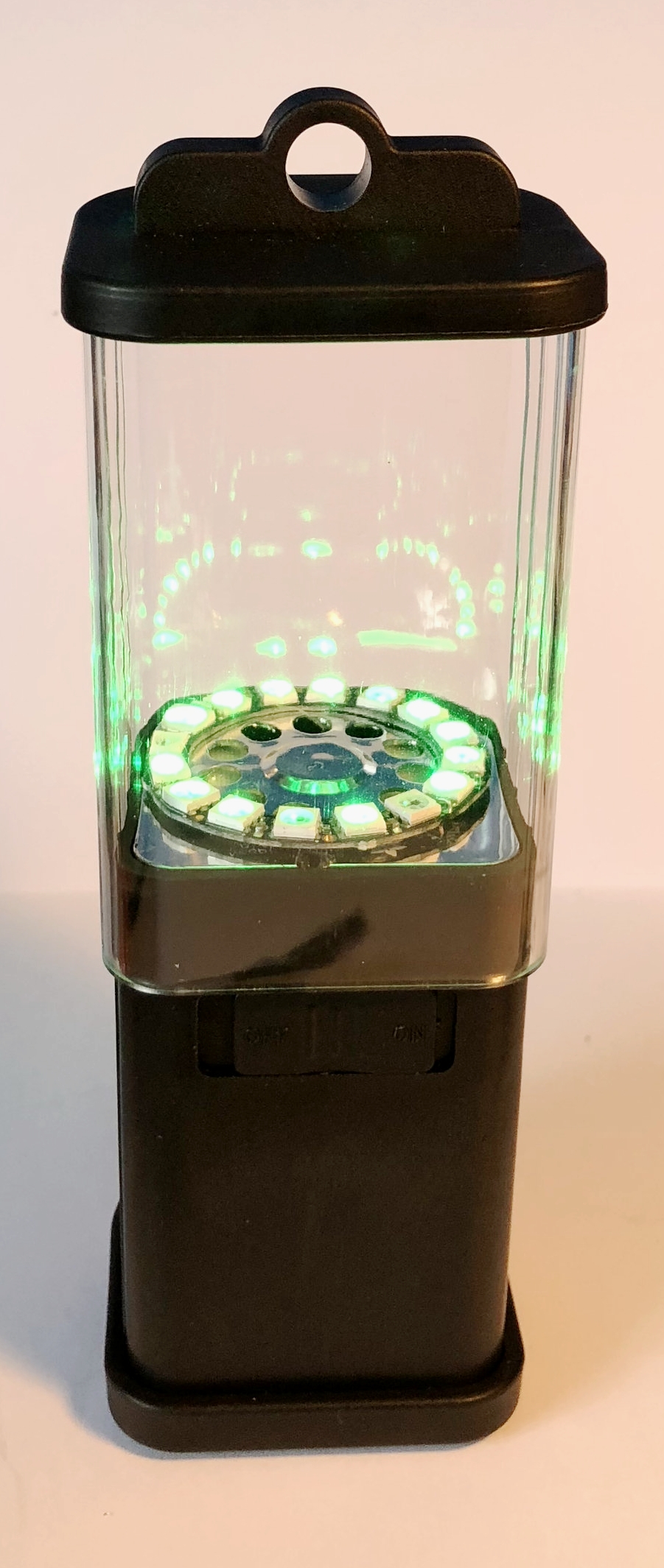
This is the light in action, just after I'd asked it to turn green.

I'm presently using MQTT to connect to the Azure IOT hub and sending text commands to configure the light. The commands are a subset of the HullOS language that I've been using on the Hull Pixelbot. Next I want to make a controller device that pushes commands up into the cloud to tell the light what to do. 

If you're looking for something to play with I can strongly recommend this light. There's a reasonable amount of space to play with - I'm thinking of adding a temperature sensor so that the light can change colour depending on how warm it is. I've discovered that I can perform my light flickering at the same time as wait for MQTT server commands and it all seems to work splendidly. I'll put the code up on GitHub when I've tidied it up a bit. 


With a bit of care you could  take the original 11 pixel ring and cut the tracks on the pcb so that each led could be controlled individually, perhaps by an Arduino Pro-Mini to get a really cheap controllable light device. 

Make your own Theremin. Sort of.

A Theremin is a musical instrument that you control by waving your hands. It's used a lot to provide spooky sounds for science fiction and horror movies. A "proper" theremin uses a tuned circuit that is which is controlled by the player waving their hands near a couple of antennas. 

I thought we could have a go at making something similar using just a light sensor and an Arduino, so I've come up with the circuit above to get started. You can find the detailed instructions here. We've been using these little exercises at the c4di Hardware Group, which met again today and will meet again on Thursday 5th July. Sign up here if you want to come along and make some annoying noises....

Working with the Arduino at the Hardware Group

I really must take more, or at least some, pictures of the Hardware Group at c4di in action. But I'm always too busy talking about stuff to get out the camera.

Anyhoo, we had a great meetup today. We've got a bunch of new members who are just getting started, so we've put together some tiny hardware kits that they can use to get started. Like those "Build an Aston Martin in easy steps" magazines that you can buy in the new year, If you want to pick up a kit and have a go, come along to our next meetup on the 7th of June. You can sign up here

Hull Raspberry Pi Jam with robots

Well, that was great fun. Spent the morning at the Hull Raspberry Pi Jam. It was something of a "RobotFest". I had my Hull Pixelbots and Coretec Robotics were there with their balloon Raspberry Pi powered balloon busting robots. I was trialling a new idea I've had, called the "Robot Rumble". The idea is that players code up their robot warriors to get as far into their opponents area as possible. You can find the draft rules here

As it turned out we didn't get that many rumbles going, but folks had great fun making their robots do things, including some things I'd never have thought of, which was rather nice. And from the sounds of bursting balloons and cries of victory coming from the other side of the library, fun was being had there too. 

The second part of this post was going to have the title "Three Thing Game Judging Fun". But instead I'd have to use the title "I probably shouldn't have eaten that chicken from the fridge". Number one wife did ask me to check the sell by date but I was confident it was fine. And besides, I'd thrown the package away.

By 2:30 it was turning out that the chicken might not have been that fine after all. And an attempt to "kill or cure" by drinking a can full of "Old English Ginger Beer" didn't have the desired effect. Which meant I had to beat a hasty retreat from the event and head home for a lie down amongst other things. 

Fortunately the effects don't seem to have been too long lasting, which is a good thing as I'm supposed to be driving to Birmingham tomorrow. 


esp8266 wacky wifi

one way to get a screenshot....

This is rather weird. It all started when I got my old Nexus 7 tablet out of retirement. I'm doing some upgrades for the web server for the Raspberry Pi event coming up, and I wanted to use the Nexus to see if the web site would work on an Android powered browser. 

One of the applications on the Nexus is a WiFi analyser that I've used to pick and choose my WiFi channels. When I fired it up I noticed a few strange transmitters which were taking over the spectrum (as you can see above). 

I finally tracked this down to the esp8266 devices that I use in Hull Pixelbots. For some reason, when they wake up, they start doing things on WiFi channels. I've no idea of the precise meaning of this transmission, but I don't particularly like it. It turns out that if you turn off the WiFi before you do anything else (even turn it back on to connect to an access point) then you don't see this. 

I'd love comments from anyone else who've seen this, or has more knowledge of what is going on. In the meantime all my programs now start with:

WiFi.mode(WIFI_OFF);

Arduino Retro Computer

Derek put me onto this. It's a retro computer made from two Arduino devices, one of which generates VGA output. Many years ago I discovered that people were using PIC devices to produce video output, this does something similar with an Arduino to generate VGA video. It uses a tiny interpreted basic that is not a million miles away from my HullOS software, although the Basic implementation uses a lot more gotos....

"In-band" error signalling is dangerous

I've been working on the Hull Pixelbot for what seems like ages (You probably think I've been blogging about it for roughly as long. Don't care. My blog.)

Anyhoo, today I learned the perils of "in band error signalling". The phrase "In-band" is a radio term. It means that control information is sent in the came channel as the data. My "in-band" errors worked like this:

int findVariablePos (char * name)
{
    int result;
     /* Stuff happens in here to find the variable  */
    return result; // return the offset of the variable */
}

The function findVariablePos returns the offset into the variable name table of the variable with the given name. In a program a variable is a named location that you can use to store data that is used as the program runs. If my program does this:

i = 99

- this is an attempt to store 99 in a variable called 'i' for no readily apparent reason. The thing running the program needs to have a way of finding out where in the computer the variable i is actually stored. That's the job of findVariablePos. Deep inside the program that actually runs the Hull Pixelbot script there is a statement like this:

int iPos = findVariablePos ("i")

The statement above (we're writing C by the way) would get me the position in the variable table of the variable with the name 'i'. "Aha", you say. "What if the program doesn't contain a variable called 'i'. ". Well, in that case the findVariablePos function returns the value -1 to indicate that the name was not found. This is kind of sensible, because you can't have anything at the position -1 in a table, negative numbers are meaningless in this context. All good. To make things clearer I even did this:

#define VARIABLE_NOT_FOUND -1

This gives meaning to the value, so that I can write tests that make sense:

if (iPOS==VARIABLE_NOT_FOUND)
{
    Serial.println("Variable not found");
}

All good. Works fine. Then I re-factor the code and add a bunch of new error codes. I then decide it would be nice to have a set of numbers that the user (and other programs) can use to make sense of error messages. And I make the following change:

#define VARIABLE_NOT_FOUND 2

This makes sense in the context of fiddling with my error numbers, but it means that if the program ever puts a variable in location 2 in the variable table, the program will completely fail to find it because every time it gets the offset value this will be regarded as meaning that no variable was found. 

Which is of course what happened. The problem in caused by a bad design decision (using the data value as a means of signalling errors) and then doing something without considering the consequences. The latest version of findVariablePos looks like this:

int findVariablePos (char * name, int * position)
{
    int result;
     /* Stuff happens in here to find the variable  */
    
    *position = result;
    return FOUND_OK;
}

The result of the call is returned via one channel (the result of function) and the position value is returned by the method setting the value of the second parameter, which is a pointer to the variable. The call is a bit more complicated:

int iPos;
if (findVariablePos ("i",  &iPos) == FOUND_OK)
{
    Serial.println("Found the variable");
}

However, it now doesn't matter what the error numbers are, and whether or not they clash with any valid variable positions. 

"In-band" error handling is great if your'e in a hurry and you're trying to keep the code simple and quick. But they also leave you open to problems further down the tracks. 

World's Smallest Arduino compatible board at c4di Hardware Group

Did you know that the worlds smallest Arduino compatible device is made in Hull? I didn't until Hayden turned up with one at the hardware group at c4di tonight. He's designed and built a lovely little device. I've played with tiny Arduinos before. They are usually a bit hard to connect to a computer because they lack a proper usb connection and are a bit under-powered when you get them going. 

The device that Hayden has made gives you serious computing power in a device you can hang off any micro-usb cable and program using the standard Arduino SDK. It puts a 48 Mhz  device with 256K of ROM and 32K of RAM onto your fingernail. You can find out more (and buy one for yourself) here. We had it flashing a led, which is probably not really the best use of its power, but it is a start....

It was a great meetup. We had some new folks turn up keen to learn, and some who had brought things to talk about. You can sign up for the next one on Thursday 7th December (and you should) here.

Arduino vs One Drive

Some things you just have to learn the hard way. For a while I've been frustrated by the way that my Arduino projects would build fine for a while, and then fail after I had saved them. 

Eventually I worked out that if you're working on a folder which is being shared by One Drive (or DropBox and probably Google Drive) this causes the Adruino SDK to get upset when it tries to build a solution. This must be due to the file sync process causing files to be locked when they shouldn't be.  Move the files to your desktop and the program builds perfectly. 

Of course, the proper way to share a development project between a bunch of machines is to use GitHub, and that's what I'll be doing in the future....

Buy this Arduino Book

If you're looking for a book about the Arduino that is stunning value for money, just head out to your local newsagents and track down a copy of the latest Teach In from Everyday and Practical Electronics (or EPE). It provides an excellent introduction to the Arduino device and then, as a bonus, adds a bunch of chapters about PIC development and some other good stuff.

Like all of the EPE publications, this is well written, technically accurate and laid out in an easy to read manner. And you even get a CD-ROM with lots of useful stuff on it too. 

Full Disclosure: Many years ago I helped Ian and Tony to write a Teach-In for the magazine. It's nice to see that Ian is still writing for them, there's a lovely piece from him about state machines in the back of this very publication. 

A must-buy in my opinion.

HullPixelbot Code takes shape

Building on the work yesterday, I've now made a little code editor that can be used to control the HullPixelbot motor controller. You can load and save programs and send them via a serial port into an Arduino. The programs are stored in EEPROM inside the device, so that they run when the robot starts up. Next step is to distribute the programs over MQTT using the esp8266. Then I'll be a lot closer to my dream of autonomous robots that I can easily reprogram.

The program above starts a movement and then tests a conditional branch behaviour that fires when the motor stops running. You can use this to write code that starts the robot moving and then responds to events.

The nice thing about the programs so far is that they are very frugal. I've got everything running on a single Arduino Pro-Mini and it seems to work OK at the moment.

Potential Dividers for Pixelbots

..a divider with potential

I've been working on the HullPixelbot hardware today. I want to use an HC-SR04 distance sensor so that a robot can detect when it is getting close to something. These devices are not perfect, but they are very cheap (less than a pound from China). Snag is they are 5 volt devices (i.e. they are powered by, and produce signals at, a 5 volt level).

The Arduino Pro-Mini that I'm using to control the motors and sensors is a 3.3 volt device. Directly connecting a distance sensor to it would not end well. It might actually break the Arduino. There are special converter chips thatyou can buy to addressthis, but they are expensive and need to be wired up. Fortunately the only signals you need to worry about are those going into the Arduino, and the only input signal is the echo pulse. So I just have to adjust the level of that signal.

The way that the sensor works is that you give it a signal to say "please measure the distance". The sensor then makes an ultrasonic "squeak" and times how long it takes for the squeak to bounce back. It generates a pulse, called the echo signal that represents this time. The longer the echo pulse, the longer it took for the sound to bounce back, and the further away the target is from the sensor.

The echo signal provided by the distance sensor is either at 0 volts or 5 volts. We want to convert the 5 volt value to 3.3. I've used a potential divider to do this. This uses the principle that the voltages in a circuit are distributed according to the resistances in each element. The higher the resistance of one part of the circuit, the more volts are "dropped" across this part. This probably doesn't seem sensible, but it is how a lot of electronic devices work.

In the old days we used to use lots of low voltage bulbs in our Christmas lights. The mains voltage of 240 volts would be spread over, say 20 bulbs, each designed to work with 12 volts. All the bulbs were connected in a chain, so the voltage dropped across each bulb was 12 volts (a twentieth of 240). Bad news, if one of the bulbs fail the whole chain goes out.

Worse news, if a human being (who has a resistance a lot higher than a 12 volt bulb) puts themselves into the circuit trying to fix this they will find that nearly all the voltage is dropped across them, which is how until recently Christmas was always accompanied by grisly stories of people electrocuted when they were fixing the lights on their tree.

Anyhoo, back to the robot circuit. The total resistance of our two resistors is around 3K. The voltage dropped across the 1K resistor will be around the third of the 5 volt input. These are the volts I don't want. The voltage across the 2K resistor will be around two thirds of 5 volts, which is as near 3.3 volts as makes no difference. And it works, which is nice.

If you think about it, what I've made is a machine that can divide by 3 at close to the speed of light. Any signal going into the potential divider will be divided by 3 on the output because physics. The speed of these two resistors massively outperforms even the most powerful of digital computer, and so-called "analogue" computers like this were much used in the past.

Visual Micro Still Rocks

I bought Visual Micro a while back. Not that I really needed to. The free version is actually plenty powerful enough for day-to-day use. It was just that I thought the product was so good that I really should support it.

For a registration you get a key that works on three machines. I've been through a few machines over the years (as you do) and last week I found that my key didn't work for my desktop. I emailed them, they cleared the key and I'm back in business again. Thanks folks. 

If you are in any way serious about embedded development you should get this tool. The free Arduino SDK is OK for a while, but you'll fairly quickly hit limitations that will grate, and with Visual Micro you get all the lovely intellisense support and general niceness that comes with developing code in Visual Studio.

Visual Micro now works with all the esp devices and pretty much anything Arduino shaped as well. It's got some very interesting debugging support too, but I tend to rely on code instrumentation (print statements) when I'm writing embedded code, so I don't use it very much. Go get it. 

Hull Pixelbot Version 2.0

I've just released a new set of design files for the HullPixelBot. I've made some improvements and also added holders for the pixel lights (always useful in a pixelbot) and the distance sensor. I was quite proud of the design for the distance sensor holder, until I tried to use it. 

I thought I'd been clever by providing mounting slots for the distance sensors so that the wires could come through the slots for the connections on the back. Turns out this was actually stupid. It turned out to be really hard to make the connections with the hole. 

The new design (which you can see above) has separate holes for the two sensor wires, and they are arranged vertically so you can just connect all the bottom wires together to a common ground (or reference voltage) and then take each of the top wires and connect them to their potential divider resistor and reference voltage (or ground). I'll be doing a detailed post about wiring things up a little later. 

Putting the Pixel into HullPixelBot

The idea behind HullPixelBot is that it is a roving pixel robot. From Hull. We've got the robot part working quite nicely now, with motors and wheels and everything. But we've been missing the pixel bit. So today I spent some time crafting the holders for the pixels mounts.

The plan is to have two pixels on a robot.. One on the top, directly between the two wheels. We can use this to "draw with light" and whatnot. The other pixel is mounted on the back of the robot. On the front of the robot we are going to put a light sensor so that a robot can find and follow another robot with a particular coloured pixel on the back.

I'm going to spend the next day or so fiddling with the design and printing test versions to make sure it all fits together. Exciting stuff.


HullPixelBot on WiFi

We had a pretty good turnout tonight at the C4DI hardware group. The focus was on building and powering up HullPixelBots. I'd printed a few sets of parts and some folks had even turned up with all the other bits, so we made some robots from scratch. Important lesson learned, make sure that you link the two pins on the motor driver board If you want the motors to work. 

I even managed to get the WiFi working on the "bot with two brains". The code made the motor move when I browsed a website on the phone. From an access point hosted on the robot. My dream of a networked army of robots doing my bidding is coming closer.

Dual Processor Hull Pixel Bot

I think you should know I'm rather proud of this...

I've just finished building the prototype for the dual processor version of the HullPIxelBot. A single Arduino is a nice enough way to do simple robot control. But I want WiFi. And access points. And web servers. So I've coupled an ESP8266 device (in this case the Node MCU) up to an Arduino Pro-Mini. The Pro-Mini takes care of the low level motor control, producing the signals that will drive the steppers. The ESP8266 device doesn't really have enough pins for the motors, and it has better things to do than drive steppers, so I've linked the two with a serial connection.

Since the Pro-Mini costs around a pound and has a negligible effect on power consumption I reckon it is worth doing. At the moment we have a really simple one byte command protocol, but I can build that up a bit if I need to use the Pro-Mini to do some sensor integration. 

Next step is to work up the web side so that I can make a wireless, web controlled robot. Then we add the coloured pixels to the bot and we are really in business. 

I'll be releasing all the code and the circuit diagrams later. If you want to see the real thing, come along to C4DI tomorrow evening at 6:00 pm.