Faberdashery Space Marine Blue Looks Lovely
/
I’ve been trying some of the new PLA that I got from Faberdashery. This is Space Marine Blue and I think it looks ace.
I’ve been trying some of the new PLA that I got from Faberdashery. This is Space Marine Blue and I think it looks ace.
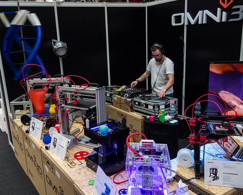
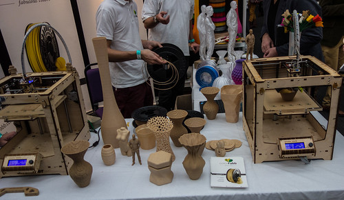
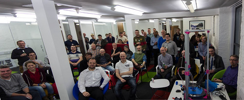
One more picture from yesterday. This stand had some amazing printers and a DJ as well.
Today I had a go at printing with some of the fibres that I got yesterday. It didn’t start well to be honest. I put in some lovely translucent green PLA that I’d been given and the printer produced some rather gooey looking outputs. Turns out the new material had a much lower melting point that the stuff I normally used. So when Una heated it up to 220 degrees I was printing with something very runny indeed. When I brought the temperature down to a slightly cooler 200 degrees things improved massively, and I ended up with some much more pleasing results.
That’s a tip for 3D printing folks. Try different temperatures. I’ve now started printing a bit cooler and my prints have a bit more detail, and the layers seem more even, which is nice.
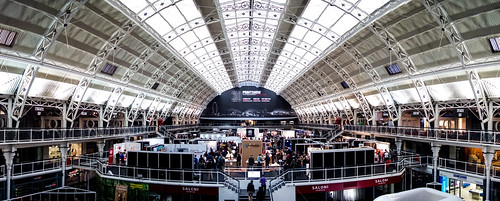
A rather nice venue
So today it was up bright and early and onto the train for a trip to the London 3D Print Show. I went last year and I enjoyed it so much I’ve gone back this year. There was a bigger venue and more stuff going on. Same mix of presentations, stands and exhibitions, but generally just more of it. The business is definitely maturing. The general thrust of things is towards are more “appliance” type devices which folks could just get hold and use to print things. There was also a stunning display of how 3D printing is being used in medicine, from printing tissue and prosthetics to making 3D mock-ups of the patient for the surgeon to practise on.
Ultimaker were there with the new Ultimaker 2 and a wall of Ultimaker 1 machines. There were lots of other brands there I’d not seen before.
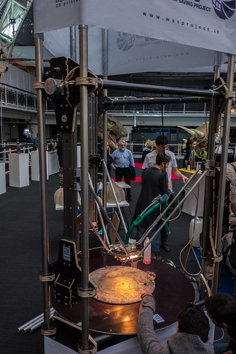
This printer was turning out pottery, which was very impressive.
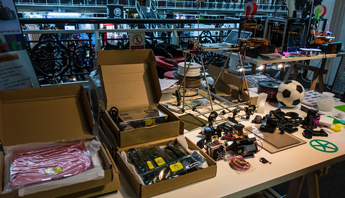
They even had people selling parts. That heated bed looked very tempting….

There were 3D printed moustaches up for grabs.
This stuff looks amazing. PLA fibre with wood particles in it.Makes prints that look like tiny carvings. I got a little sample of the stuff which will be very interesting to play with.
On the way out I went past the shop and bought a bunch of Faberdashery colours that look really nice. I’m going to have a go at printing with them tomorrow. But I might have a bit of a lie-in first.

I tend to buy all my 3D printing fibres from Faberdashery. They are by no means the cheapest, but I’ve found their quality and consistency to be very good, and they have a range of really nice colours that go well together, at least to my untrained artistic eye.
There is one little trick that the company plays that is really rather cunning. When they send you a box of fibres they always include a few metres of a colour you haven’t ordered, to play with. This is sneaky because it usually ends up with me ordering a full roll of that colour. Today I got some new fibre and found that they’d included some gold stuff. This is not just gold, it has tiny flecks in it that look really nice. The picture above doesn’t really do it justice,
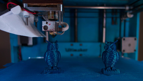
I’ve never really managed to get a happy ending when I print very small objects, they just tend to merge into one molten looking lump. However, I thought I’d have a go because if things went badly at least I’d not waste much raw materials, which didn’t cost me any money anyway. So I printed out a couple of tiny owl earrings and I don’t think they’ve turned out half bad.
A 3D printing tip: One of the things that determines the quality of the print is the “layer height”. The printer prints by laying down successive layers of plastic on top of each other. In theory, the thinner each layer the higher the resolution of the printing. My printer is supposed to be running at high quality when it prints layers which are a tenth of a millimetre thick. However I’ve found that in practice an ultra-thin layer doesn’t work very well. The print head is so close to the object being printed that it melts one layer as it puts the next on top, resulting in a sludgy looking mess. I’ve had much better results printing with thicker layers. The owls above were printed using layers that were a fifth of a millimetre in height. You can see each layer, but I quite like that, in the same way as wood has a grain, I quite like to be able to see how the object was constructed. I reckon it is worth trying to print out at with thicker layers sometimes. The printing will be quicker and it might even look nicer.
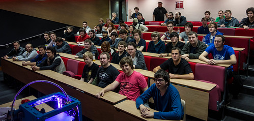
We had a good audience for the first Rather Useful Seminar. Some of them were fresh from a first year lecture and must have been feeling a mite peckish. But they stayed to the end and I hope they enjoyed it. The talk was very similar to the one I did last year, but there was a twist at the end, when I printed the weather forecast as a plastic object. Again, I brought along Una the Ultimaker, and again she behaved herself very well.
I’ve become quite intrigued with the idea of generating objects from software, and it occurred to me that with the FreeCad tool having a Python interpreter in it, we should be able to do something interesting. I’d no idea how to use Python to read a weather forecast but fortunately Catalin George Festila has done it here. So I took his methods which use the Yahoo weather feed and prints it out and made a few changes.
def weather_for_zip(zip_code):
    url = wurl % zip_code +'&u=c'
    dom = minidom.parse(urllib.urlopen(url))
    forecasts = []
    for node in dom.getElementsByTagNameNS(wser, 'forecast'):
        forecasts.append({
            'date': node.getAttribute('date'),
            'low': node.getAttribute('low'),
            'high': node.getAttribute('high'),
            'condition': node.getAttribute('text')
        })
    ycondition = dom.getElementsByTagNameNS(wser, 'condition')[0]
    return {
        'current_condition': ycondition.getAttribute('text'),
        'current_temp': ycondition.getAttribute('temp'),
        'forecasts': forecasts ,
        'title': dom.getElementsByTagName('title')[0].firstChild.data
    }
This is the code that he wrote that fetches the weather information from the Yahoo weather service and creates a list of objects that contain a forecast item for five days. The forecast information contains the highest temperature for each day, and that’s what I’m going to use to control the height of each of the columns that I print.
def main():
    a=weather_for_zip("UKXX0476")
    noOfReadings=5
    # find range of temperatures
    highest = float(a['forecasts'][0]['high'])
    lowest = highest
    for i in range(noOfReadings):
        v = float(a['forecasts'][i]['high'])
        if highest < v:
            highest = v
        if lowest > v:
            lowest = v
    # make some blocks
    plinthThickness = 3.0
    blockWidth=5.0
    blockDepth=5.0
    blockStartHeight = 5.0
    heightRange = 20.0
    rangeScale = heightRange / (highest - lowest)
    x=0.0
    y=0.0
    plinth = Part.makeBox(blockWidth*noOfReadings,blockDepth, \
        plinthThickness, Base.Vector(0,0,-plinthThickness))
    for i in range(noOfReadings):
        v = float(a['forecasts'][i]['high'])
        blockHeight = blockStartHeight + rangeScale * (v - lowest)
        block = Part.makeBox(blockWidth,blockDepth, \
            blockHeight, Base.Vector(x,y,0))
        plinth = plinth.fuse(block)
        x = x + blockWidth

    Part.show(plinth)
    Gui.SendMsgToActiveView("ViewFit")
    Gui.activeDocument().activeView().viewAxometric()

main()
The Yahoo zip code for Hull in the UK is UKXX0476. This code fetches the weather forecast data and then finds the largest and smallest temperature values (something which should be familiar to first year students). It then makes a row of five blocks, each of which has a height set by the temperature for that day. I’ve re-written it from the demonstrated code so that the coordinates make a bit more sense. The width and depth values map onto the x and y directions, with height being the z value. The code creates a little plinth and fuses a series of blocks onto the plinth. The length of each block is the temperature for that day.

This is the object that was produced by FreeCad. It represents the temperatures 12, 16,14, 17 and 16 degrees, which is the rather chilly forecast for the next few days. I sliced the design using Cura and then, after a bit of kerfuffle I managed to print out the temperature plot.
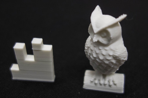
The weather forecast. And a tiny owl.
I printed it out really tiny (all of the dimension values above are in mm) but I reckon it came out quite well. I’ve since found a flaw though, in that you can’t tell which way round it is supposed to be read. Of course I could add an arrow or emboss some text to make it easier to use.
I must admit that I can’t see a huge demand for physical manifestations of the weather forecast, but I hope it brought home to folks how easy it is to grab information and turn it into something tangible. There is a lot of scope for random patterns and generating objects from mathematical formulae. And, as you can see above, it is very easy to do. I made an offer that if anyone uses Python to make an interesting object I’d be quite happy to print it out for them.
You can find the slide deck here. At the end Peter was kind enough to show some videos of his printer in action. You can find out all about the “Richmond” 3D printer at his blog here.
Well, that was fun. Peter, David, Helen, Paul and myself all got together to talk about 3D printing and scanning at C4di. I took along Una, my Ultimaker printer, David, Helen and Paul took along their 3D scanner and MakerBot printer and Peter showed off his “Richmond” printer.
Within no time the place was full of the smell of hot plastic and the sound of machines whirring away. We had a huge audience (in that there were lots of people, not that they were giants) and they seemed to really enjoy finding out about 3D printing. I started things rolling, with a quick zoom through my presentation about how I got into making things and then Peter followed up with a talk about how he came to design and build his own 3D printer from scratch. As you do.
Finally David rounded off with a description of how 3D printing and scanning technology is being used in his business and how it will undoubtedly develop in the future. Helen and Paul were showing off their modelling and scanning skills and the whole thing ended with lots of happy people wandering round, taking a look at the technology and getting to grips with it. Without getting their hands burned.
Thanks to Jon Moss for setting up the session and C4di for hosting it.
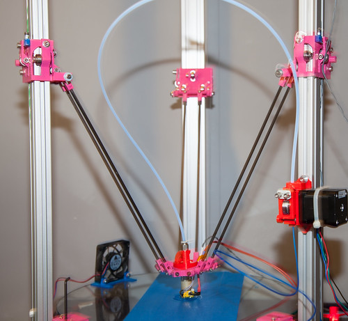
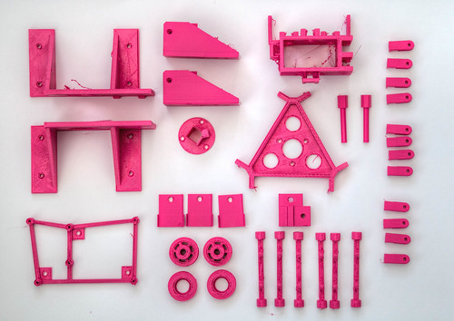
I went out this afternoon to take a look at Peter’s 3D printer. You can find out more about it here. I’ve actually seen it now. It’s awesome. The most impressive thing is that all the parts were designed by Peter and some of them were printed by me. And it works. To the point that the fan mount on the picture above was actually printed by the printer itself.
I made my printer from a kit and I’ve been slowly discovering the best way to get things from a roll of plastic fibre into a useful shape. The learning curve has been steep at times, but what Peter has done is much more tricky. He has had to construct and align all the components himself.
The design of the printer is totally unlike mine. The position of the printing head is controlled by the movement of the three carriages up and down the three pillars. The controlling software drives stepper motors that are connected to cable that is looped around each pillar and pulls the carriages up and down. The great thing about this design is that the head can move really fast, and during printing the item being printed doesn’t move at all. The tricky thing is that printing in straight lines involves all the motors making complex movement (which is not a huge problem, the software does all the tricky maths) but any inaccuracy in the movement will result in straight lines becoming curved or slanted.
Peter has spent a lot of time aligning everything and now he is getting some excellent results. Eventually he will be using his printer to make a whole new one.
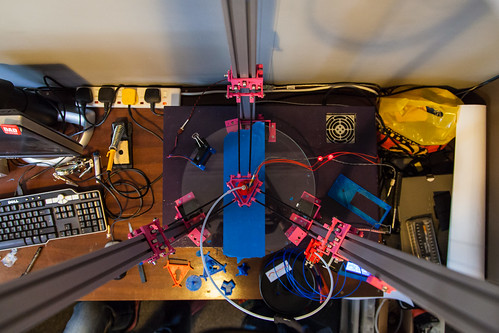
This is my favourite view of the printer.
Now, I’m not particularly old. But I can remember when the very idea of having your own printer was the stuff of dreams. Printers were places you went to when you wanted to have something printed. And as for printing in colour, that was beyond dreaming.And then the first dot-matrix and daisy-wheel printers appeared, closely followed by laser printers and finally inkjets. And now everyone has a printer.
In the early days of printing, it was a bit of a nightmare. You had to have the right kind of printer, the right kind of software and the right kind of drivers to get anything sensible. And often the thing printed didn’t match the image on the screen, or was the wrong size or shape. Eventually things settled down. Standards were set and now you can buy a printer in the confidence that it will just plug in and work with your computer.
I reckon that 3D printing is following a similar trajectory. We are at the point where hardware is appearing and we need some standards so that it can be made available to the widest possible audience. My experience with the technology has left me thinking that a 3D printer is not yet an “appliance”, but that in the longer term the attractiveness of the technology means that pretty much everyone will want a device eventually.
That’s why I’m really pleased that Microsoft have announced support for 3D printing in Windows 8.1. This is really only a step on the road to widespread adoption, but it is a really good one.
I’m doing some sessions at TechEd 2013. If you want to know how to make your Windows Phone use background agents to add value to your application, or respond to what you say, then I’m your man. I’m speaking at 10:00 am on Thursday about speech and 3:15 about background agents. And I’m going to be around at Ask the Experts too.
I had this brilliant plan for TechED US, where I’d give away 3D printed phone cases at my session. I even printed them and everything. Then I found out that the phone that I’d printed the cases for is not actually sold in the US. Which makes me an idiot.
So, instead, this time I’m giving away “I learned something from Rob” ceremonial plaques. These are completely unique, except in the sense that there are more than one of them in existence. I’ll also be giving away lovely 3D printed red rockets. So come along to my session, answer a question and you might be in the running to win.
Above you can see the 3D design for the plaque.
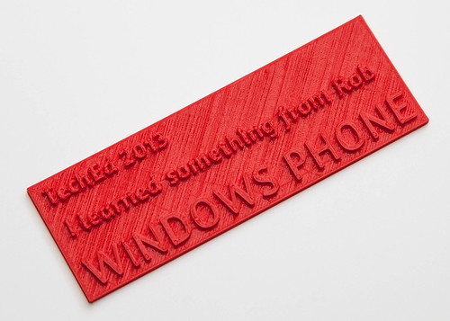
This is what the real thing looks like. With a bit of luck I might see you in Madrid, and give you one.
That could have gone better…
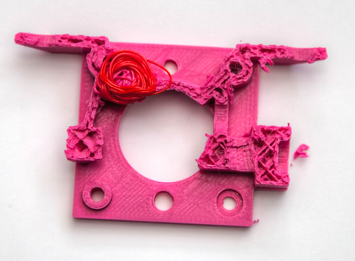
Peter is still working on his 3D printer. Today I had a go at printing another part for him. It did not end well. As you can see above, when the printer runs out of fibre to print, bad things happen.
I’ve mostly reached the point where failed prints are not as interesting as they used to be, but even so I’m tempted to hang on to this one. The problem came because I’m coming to the end of my lovely pink/magenta fibre and the last few metres are tightly wound around the inside of the spool. When they are fed into the printer the tight curves of the fibre cause more friction in the tube that pushes them into the print head. This gets harder to push, so the knurled bolt that is doing the pushing starts to slip against the fibre, eventually wearing it in two.
Then you get to strip down the feeder and extract the broken bit. Fortunately the print head wasn’t blocked, and so I was able to switch to red fibre (that little coil that looks like red hose is me forcing out the pink and sending in the red) and print all the bits with no problems.
I’m going to have to make something that straightens the pink fibre out so that I can use it.
I’ve been doing some more printing for Peter’s 3D printer. It seems like one of the principle uses for a 3D printer is to print parts for another 3D printer. I think this is probably how they are going to take over the world……
Chris (the author the above) was kind enough to send me a copy to take a look at. You can download your own from Amazon for the princely sum of 2 pounds 22 pence. If you want to know what 3D printing is all about, how it works, and some ideas about how you could build a business based on 3D printing technology I reckon it is well worth a look.
This kind of text is perfect for electronic publishing as the field is very fast moving and I hope that Chris is able to keep it up to date. The writing style is conversational and the content is packed with little nuggets of information that must have taken quite a while to put together.
You know you are an experienced 3D printer when:
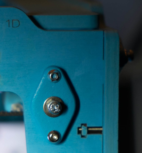
I think you should know I endured a lot of pain to fit this part…
Just because I’m on holiday, doesn’t mean I don’t get to play with tech. I spent a big chunk of today fiddling with Una, my Ultimaker 3D printer. I don’t usually give my devices names, but since I’ve discovered that this particular device has moods I thought a name would be appropriate. The great thing for me about 3D printers is that they don’t work all the time and you can always persuade yourself that there are things you can do to make them better. Perfect for a tinkerer like me, who was brought up on Meccano.
Today I convinced myself that by replacing the wooden end bearing caps with adjustable plastic ones I could probably improve print quality. I could certainly cut down on the banging and crashing that I was getting during printing, when the print head changes direction and the rods it slides on are pushed into the side of the case. I’d already made one change earlier in the week, when I upgraded the fibre feed mechanism that pushes plastic into the machine. That had improved print quality a bit and so I figured I was on a roll with this.
So I set to and printed all the parts (finding a matching colour for the case, which was nice) and then I had to fit them. This was where the fun started. I put the original fittings on as I was constructing Una, and then put lots of parts around them. This meant that the nuts holding the end caps in place were really hard to get to. I tried printing out a “nut calumet”, which sounds like a desert from a posh restaurant, but is really something you can use to put the nut on the back of the bolt. But eventually I found the best way to replace the fittings was just to jam my finger inside the machine behind each nut, so that it held it in place, undo the existing bolt and put the new one straight back in. This removes the need to put the nut in place, as it never goes anywhere, and leaving aside the pain involved in forcing your finger inside very tight spaces, worked very well.
I’m not sure if the print quality is that much better to be honest, although printing is a lot quieter and smoother than it used to be. I’m a bit worried that steel bolts in the end caps are going to grind chunks out of the steel rods they are rubbing against, so I’ve ordered some brass bolts (which cost the princely sum of 14 pence each) to replace them with. These should form a bearing against the steel and be a bit smoother.
If you have an Ultimaker then I think it is a worthwhile upgrade, just because it makes printing much quieter. If you are about to build one from a kit, I’d advise getting some end caps printed so that you can put them on during construction and save yourself a bit of pain later.
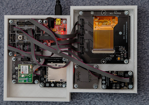
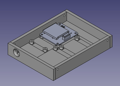
After a considerable amount of tweakage of designs and waiting for the printer to finish I now have my “Door of Mystery” machine complete. This is how it looks inside. I’ve added a WiFi card so that the door can upload pictures after they have been taken.
After all my careful planning the box needed a bit of surgery because I’d forgotten that power connector protrudes from the front of the board, but apart from that (and having to go and get some more bolts) it is now pretty much complete.
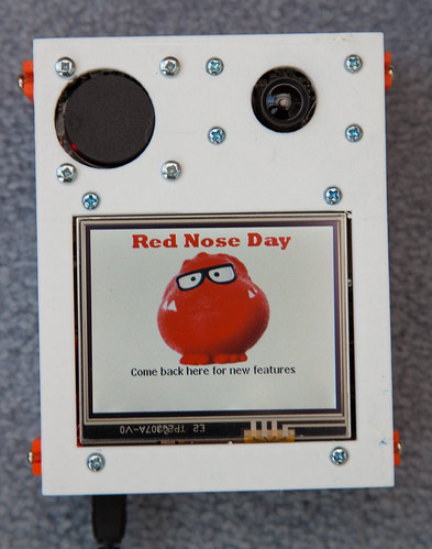
This is the finished device. I’m going to have to slightly adjust the hole for the RFID reader in the next version, but it is quite pleasingly solid and works a treat.
You buy an RFID tag to enter the competition, show it to the “Door of Mystery” above and it will give you your entry number and take your picture. Then, I can use my special “Pick a Winner” tag to pick a random entry and even view their picture. We might even use this for bashes, where we might want to give out random prizes, pick team members or let people take it in turns to use some of the games.
So today I had a go at printing out my designs. Above you can see the result. And I’d made a mistake that I’ve made before. I made the holes exactly the same size as the things intended to fit into them.
Do. Not. Do. This.
Of course they don’t fit. One thing just sits on top of the other looking exactly the same. Wah. I did think I could solve the problem by filing a bit off. Not a win.Turns out that PLA is actually quite tough stuff. After about ten fruitless minutes and quite a bit of pain (who knew you could get splinters from plastic things) I gave up and went back to the software. The good news is that I just have to tweak a couple of values and rebuild everything. I’ve even added a feature where objects can cut holes in the entire finished piece, so that the SD card and the screen can cut slots for themselves.
Ongoing.
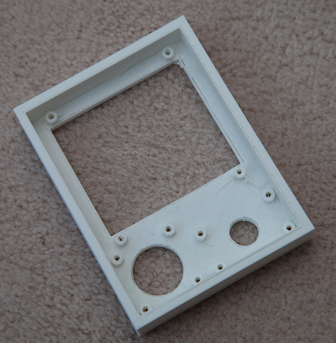
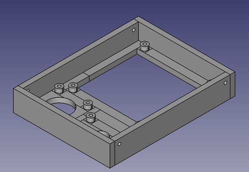
This is the base design I came up with. You can also see one of the Gadgeteer part designs where it will be fitted in the finished product.
I’ve been designing a box for the “Door of Mystery” Gadgeteer device that I built for the Red Nose Day event. But I’m very lazy. I don’t want to have to lay out the various elements by hand and position them individually. I want this to happen automatically. So I’ve wanted to write a program to do this. Peter likes OpenSCAD, so I went there first. OpenSCAD lets you create 3D images programmatically. It is really easy to use, and you can preview your designs very quickly.
module panel(width, height, x, y)
{
    translate([x,y,0])
    {
         cube(size=[width, height, baseDepth]);
    }
}
I used this tiny snippet of OpenSCAD to place a panel on the drawing surface. I move the axis to the position of the panel and then create a box of the required size. You can perform unions to merge things together and differences to cut one shape from another. In no time at all I was programmatically creating bases for the Gadgeteer devices. And then I hit a brick wall. What I really wanted to do was have the program work out where each device goes in relation to the other ones and lay out the box contents.To do that my program has to keep track of where things have been put. This means that I need some variables.
OpenSCAD does not provide variables as such. It provides constants (such as baseDepth above) but these are evaluated at compile time, and so I can’t use them to keep track of things as the program runs. This is not necessarily a criticism of OpenSCAD, it isn’t really meant to run programs, but it does mean I can’t use it.
So I went back to my old friend FreeCAD. I first used this ages ago, when I made the case for my Tweet Printer. FreeCAD can be controlled by Python programs and I’ve always fancied learning a bit of Python, so of I went. The designer has a Python console into which you can paste and run lumps of code. You can also add libraries and user interfaces on top, but I was happy to cut and paste for now. All the actions you take in the designer are exposed as Python calls via the console, which makes it quite easy to figure out how to do things. You just do it in the designer and then look at what comes out on the console. There is also an API reference which tells you how the commands work.
def makeBoard(self,x,y):
    b = Part.makeBox(self.width,self.height, 5, Base.Vector(x,y,0))
    return b
This method is a member of my “Filler” class which places the filler (which has a width and a height) at a particular place on the design. Note that the filler is 5mm thick in the above code. The program can take the object that is returned and fuse or cut it with other shapes as you build up the finished design. By the end of all my fiddling I’ve got a class hierarchy of Gadgeteer device specifications and a layout engine that will place them in a box of a particular size.
def MakeTop():
    doc=FreeCAD.newDocument()
    f1 = Filler("Filler", 5,25)
    f2 = Filler("Filler", 6.5,25)
    f3 = Filler("Filler", 6.5,20)
    rfid = RFIDReader("rfid", "landscape")
    camera = Camera("camera", "landscape")
    display = DisplayT35("display", "portrait")
    topComponents = [rfid,f1,camera,f2,display,f3]
    test = Layout(91,121,topComponents)
    board = test.layout()
    Part.show(board)
    Gui.SendMsgToActiveView("ViewFit")
    Gui.activeDocument().activeView().viewAxometric()
The MakeTop method creates the top of the box which contains an RFID reader, a touch display and a camera. These are laid out in an area with a dimension of 91x121 mm. Each component can be either “landscape” or “portrait” orientation and you can create filler elements to push things around in their row. The design method is given a list of components and an output area. The finished design looks like this:
These elements cut extra holes for themselves so that they show through the front of the box. The layout method also creates the sides and puts fixing holes in them, so that I can join the top and the bottom together. If I want different size of panel thicknesses I just change the static members that control these values and run the method again. If I want to make a different design I just create a new method which contains the devices that want.
The system is not completely automatic, what I end up doing is fiddling with the output from the method and then changing the orientation and adding fillers until I get what I want. The good news though is that it provides a really quick way of making Gadgeteer boxes. I’m going to have a go at printing the designs later in the week.
I find it fascinating that I’m now writing programs where the output is a physical artefact. We do live in interesting times.
Peter is building a 3D printer.He fancies a Rostock configuration. He has been doing some design work using OpenScad. Today he brought some designs round and we had a go at printing them. Lessons learnt, rounded corners are hard work. The printer builds objects layer by layer and if the edges are curved it seemed to make it harder to just print the outer layers. Peter was able to rearrange the drawing really easily and we had a go at printing again. The output looks like it might prove the basis of a print head. The next thing to do is print some of the side struts and the carriages that go up and down the pillars.
My printed case, and Joanna. The cutout for the camera fits absolutely perfectly.
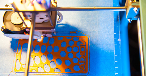
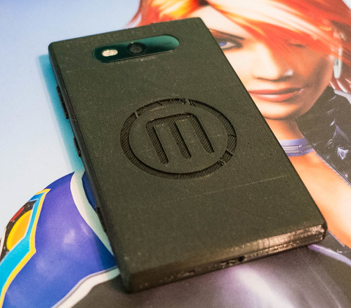
BrianT popped a comment on the blog last week about the Lumia printing templates that Nokia have just released. They can be used with a 3D printer to allow you to print your own shells for the Lumia 820 phone. You get designs for the shell plus the buttons. You can download them here. What with having a Nokia 820 and a 3D printer to play with I thought I’d had a go. Initial results weren’t successful because the back section is very slightly curved in the original Nokia designs, which for a 3D printer like mine is impossible to print (although other kinds of printers will do this kind of shape). However, a chap on Thingiverse has created a Makerbot version of the case with a flat bottom. This prints a treat, as you can see above. The only thing I don’t like is the Makerbot logo, what with me having an Ultimaker printer and all. But I can fix that by spending a few minutes in FreeCAD. In fact I can put whatever I like on there. In any colour I like.
The shell snaps onto the phone just like a “proper” one and I was very surprised to find that even the tiny buttons fit well and work OK, although I’m going to have to do a bit of trimming to make them move smoothly.
Remember that the lack of a 3D printer doesn’t stop you from making your own unique phone cases. Places like Sculpteo will take your designs and print them, including full colour if you really want it. Kudos to Nokia for making these drawings available for anyone to use.
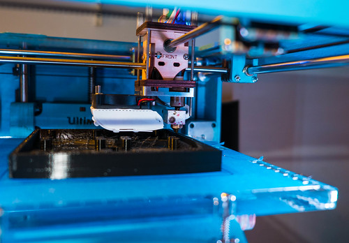
Spent some time today doing some 3D printing with the Ultimaker. And by some time I mean quite a while.
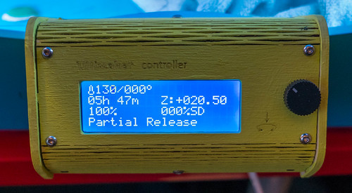
Nearly a six hour print, one of my longest so far
I’m making an enclosure for a set of Gadgeteer LED Matrix Modules from GHI. I want to combine four of them to make a 16x16 dot LED display. Once I’ve built it and got them working I’ll figure out what to do with them. I spent a while last week printing out version one of the enclosure. Rather stupidly, I made this exactly the right size, i.e. 120mm wide internally. I figured that since the units were 60mm in size each that would work fine. Not so. It made them just the right size to not fit. It is a testament to the Ultimaker printer that they would not fit either way because they were exactly the same size as the opening in the enclosure. Darn.
So it was out with FreeCad and away to design a new enclosure with an extra mm all round, so that I could actually get the units into it. I also added some support pillars that engage with the Gadgeteer boards behind each display. What I need now are some really slim nuts so that I can bolt the displays in place.
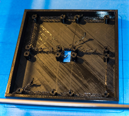
This is the finished print, complete with “sprue” that I’ll have to clean off. It took me ages to prise it off the blue tape. I think I need to adjust the platform a bit to make the top layer a bit smoother although, for this build, you don’t actually see this bit.
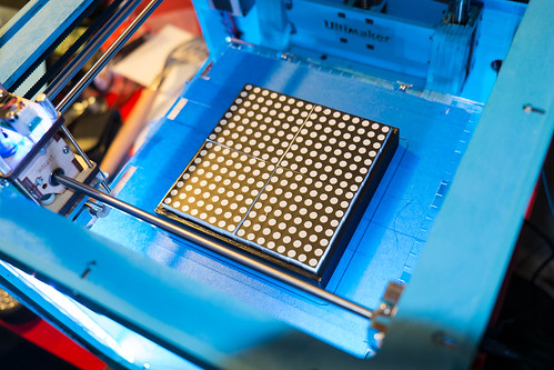
Here is the tray with the LED units fitted.
Rob Miles is technology author and educator who spent many years as a lecturer in Computer Science at the University of Hull. He is also a Microsoft Developer Technologies MVP. He is into technology, teaching and photography. He is the author of the World Famous C# Yellow Book and almost as handsome as he thinks he is.
Begin to Code with JavaScript is now available for purchase and download. You can find it here